前言
PWM 脈衝寬度調變(Pulse Width Modulation)是嵌入式系統中最常見的控制技術之一。從 LED 調光、馬達轉速控制、伺服馬達角度到開關電源,PWM 以其簡單、高效、數位友善的特性,成為每個嵌入式工程師必須掌握的技能。STM32 的 Timer 模組支援多通道 PWM 輸出,ESP32 的 LEDC 與 MCPWM 更是專為 PWM 設計。本文將從 PWM 的基本參數講起,搭配 WaveDrom 時序圖解說,最後提供 STM32 和 ESP32 的完整實戰程式碼。
一、PWM 基本概念
1.1 PWM 的三個核心參數
| 參數 | 說明 | 單位 | 範例 |
|---|---|---|---|
| 頻率 (Frequency) | 每秒週期數 | Hz | 1 kHz = 1000 次/秒 |
| 週期 (Period) | 一個完整週期的時間 | 秒 | T = 1/f = 1ms |
| 工作週期 (Duty Cycle) | 高電位時間佔週期的比例 | % | 50% = 一半時間 ON |
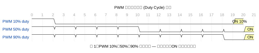
圖 1:PWM 不同工作週期比較 — 同頻率下,10%、50%、90% duty 的 ON 時間比例不同,輸出有效值也不同。
1.2 頻率 vs 週期
T_PWM = 1 / f_PWM
T_ON = Duty × T_PWM
V_avg = Duty × V_CC
圖 2:PWM 頻率比較 (50% Duty) — 頻率越高週期越短,1kHz、500Hz、200Hz 在同 duty 下 ON 時間不同。
1.3 頻率選擇原則
- LED 調光:1~5 kHz(太低會閃爍,人眼可見 flicker)
- DC 馬達:50~500 Hz(太低會產生噪音與震動)
- 伺服馬達:50 Hz(標準航模伺服規格)
- 開關電源:100~500 kHz(Buck/Boost 內建 PWM)
- Class D 音訊:200 kHz ~ 1 MHz(需濾波還原)
二、Timer 產生 PWM 的原理
PWM 訊號由硬體 Timer 自動產生,不佔用 CPU 資源。原理如下:
- Timer 計數器從 0 遞增至 ARR(Auto-Reload Register)
- CCR(Capture/Compare Register)儲存比較值
- 當 CNT < CCR 時,輸出 HIGH
- 當 CNT ≥ CCR 時,輸出 LOW
- CNT 歸零時重新開始,自動產生 PWM 輸出

圖 3:Timer 計數器與 PWM 輸出 (ARR=9) — CNT 從 0~9 遞增,CCR=3 時 duty=40%,CCR=7 時 duty=70%。
計算公式:
PWM_Freq = Timer_Clock / (PSC + 1) / (ARR + 1)
Duty = (CCR + 1) / (ARR + 1) × 100%
解析度 = 1 / (ARR + 1) × 100%
範例:STM32F4 @ 84 MHz,目標 1 kHz PWM,50% duty:
PSC = 83  →  Timer Clock = 84MHz / 84 = 1 MHz
ARR = 999 →  PWM Freq = 1MHz / 1000 = 1 kHz
CCR = 500 →  Duty = 501 / 1000 ≈ 50%
三、STM32 PWM 實作 (HAL + Timer)
3.1 CubeMX 配置
- Timer2 設定:Clock Source = Internal Clock
- Channel1 = PWM Generation CH1
- Prescaler = 83 (84-1), Counter Period = 999 (1000-1)
- Pulse (CCR) = 500 (初始 50%)
- GPIO: PA0 = TIM2_CH1 (AF1)
3.2 初始化程式碼
#include "stm32f4xx_hal.h"

TIM_HandleTypeDef htim2;

void MX_TIM2_Init(void)
{
    TIM_OC_InitTypeDef sConfigOC = {0};

    htim2.Instance = TIM2;
    htim2.Init.Prescaler = 83;          // 84 MHz / 84 = 1 MHz
    htim2.Init.CounterMode = TIM_COUNTERMODE_UP;
    htim2.Init.Period = 999;            // 1 MHz / 1000 = 1 kHz
    htim2.Init.ClockDivision = TIM_CLOCKDIVISION_DIV1;
    htim2.Init.AutoReloadPreload = TIM_AUTORELOAD_PRELOAD_ENABLE;
    HAL_TIM_PWM_Init(&htim2);

    sConfigOC.OCMode = TIM_OCMODE_PWM1;
    sConfigOC.Pulse = 500;              // 50% duty
    sConfigOC.OCPolarity = TIM_OCPOLARITY_HIGH;
    sConfigOC.OCFastMode = TIM_OCFAST_DISABLE;
    HAL_TIM_PWM_ConfigChannel(&htim2, &sConfigOC, TIM_CHANNEL_1);
}

void HAL_TIM_PWM_MspInit(TIM_HandleTypeDef *htim)
{
    GPIO_InitTypeDef gpio = {0};
    __HAL_RCC_TIM2_CLK_ENABLE();
    __HAL_RCC_GPIOA_CLK_ENABLE();

    gpio.Mode = GPIO_MODE_AF_PP;
    gpio.Pull = GPIO_NOPULL;
    gpio.Speed = GPIO_SPEED_FREQ_LOW;
    gpio.Alternate = GPIO_AF1_TIM2;
    gpio.Pin = GPIO_PIN_0;
    HAL_GPIO_Init(GPIOA, &gpio);
}

void start_pwm(void)
{
    HAL_TIM_PWM_Start(&htim2, TIM_CHANNEL_1);
}
3.3 運行中調整 Duty
void set_duty(uint8_t percent)
{
    if (percent > 100) percent = 100;
    uint32_t ccr = (uint32_t)percent * 999 / 100;
    __HAL_TIM_SET_COMPARE(&htim2, TIM_CHANNEL_1, ccr);
}

// 呼吸燈效果
void breathe_effect(void)
{
    for (int i = 0; i <= 100; i++) { set_duty(i); HAL_Delay(10); } for (int i = 100; i >= 0; i--)
    {
        set_duty(i);
        HAL_Delay(10);
    }
}
3.4 多通道 PWM(互補輸出 + Dead Time)
// TIM1 進階定時器支援互補輸出,適合 H-Bridge 馬達控制
// CH1 = PA8, CH1N = PB13 (互補), CH2 = PA9, CH2N = PB14

sConfigOC.OCMode = TIM_OCMODE_PWM1;
sConfigOC.Pulse = 500;
sConfigOC.OCPolarity = TIM_OCPOLARITY_HIGH;
sConfigOC.OCNPolarity = TIM_OCNPOLARITY_HIGH;
sConfigOC.OCFastMode = TIM_OCFAST_DISABLE;
sConfigOC.OCIdleState = TIM_OCIDLESTATE_SET;
sConfigOC.OCNIdleState = TIM_OCNIDLESTATE_RESET;
HAL_TIM_PWM_ConfigChannel(&htim1, &sConfigOC, TIM_CHANNEL_1);

// Dead Time 設定 (BDTR 暫存器)
htim1.Init.DeadTime = 10;  // 100ns dead time (取決於 Timer clock)
HAL_TIMEx_PWMN_Start(&htim1, TIM_CHANNEL_1);  // 啟動互補輸出
四、ESP32 PWM 實作
ESP32 有兩套 PWM 硬體:LEDC(通用 PWM)和 MCPWM(專用於馬達控制)。
4.1 LEDC 基本 PWM(Arduino)
#include <driver/ledc.h>

#define LEDC_CH    LEDC_CHANNEL_0
#define LEDC_TIMER LEDC_TIMER_0
#define LEDC_PIN   2  // GPIO2 (內建 LED)
#define LEDC_FREQ  5000  // 5 kHz
#define LEDC_RES   10     // 10-bit 解析度 (0~1023)

void setup()
{
    ledcSetup(LEDC_CH, LEDC_FREQ, LEDC_RES);
    ledcAttachPin(LEDC_PIN, LEDC_CH);

    // 呼吸燈
    for (int duty = 0; duty <= 1023; duty++) { ledcWrite(LEDC_CH, duty); delay(2); } for (int duty = 1023; duty >= 0; duty--)
    {
        ledcWrite(LEDC_CH, duty);
        delay(2);
    }
}

void loop()
{
    // 外部控制
    int pot = analogRead(34);  // 電位器 0~4095
    int duty = map(pot, 0, 4095, 0, 1023);
    ledcWrite(LEDC_CH, duty);
    delay(20);
}
4.2 LEDC ESP-IDF 框架
#include "driver/ledc.h"
#include "esp_err.h"

#define LEDC_GPIO    GPIO_NUM_2
#define LEDC_FREQ    5000
#define LEDC_RES     LEDC_TIMER_10_BIT

void pwm_init(void)
{
    ledc_timer_config_t timer_conf = {
        .speed_mode      = LEDC_HIGH_SPEED_MODE,
        .timer_num       = LEDC_TIMER_0,
        .duty_resolution = LEDC_RES,
        .freq_hz         = LEDC_FREQ,
        .clk_cfg         = LEDC_AUTO_CLK,
    };
    ledc_timer_config(&timer_conf);

    ledc_channel_config_t ch_conf = {
        .gpio_num   = LEDC_GPIO,
        .speed_mode = LEDC_HIGH_SPEED_MODE,
        .channel    = LEDC_CHANNEL_0,
        .timer_sel  = LEDC_TIMER_0,
        .duty       = 0,
        .hpoint     = 0,
    };
    ledc_channel_config(&ch_conf);
}

void set_pwm_fade(uint32_t target_duty, int time_ms)
{
    ledc_set_fade_with_time(LEDC_HIGH_SPEED_MODE,
        LEDC_CHANNEL_0, target_duty, time_ms);
    ledc_fade_start(LEDC_HIGH_SPEED_MODE,
        LEDC_CHANNEL_0, LEDC_FADE_NO_WAIT);
}
4.3 伺服馬達控制 (50 Hz)
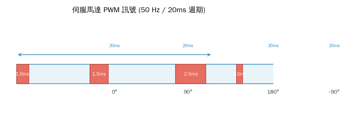
圖 5:伺服馬達 PWM 訊號 (50 Hz / 20ms 週期) — 0°=0.5ms、90°=1.5ms、180°=2.5ms。
#include <ESP32Servo.h>

Servo myServo;
#define SERVO_PIN 13

void setup()
{
    myServo.attach(SERVO_PIN, 500, 2500);  // min=500μs, max=2500μs
}

void loop()
{
    myServo.write(0);    // 0°
    delay(1000);
    myServo.write(90);   // 90°
    delay(1000);
    myServo.write(180);  // 180°
    delay(1000);
}
ESP-IDF 使用 MCPWM 控制伺服馬達:
#include "driver/mcpwm_prelude.h"
#include "driver/mcpwm_timer.h"
#include "driver/mcpwm_oper.h"
#include "driver/mcpwm_cmpr.h"
#include "driver/mcpwm_gen.h"

void servo_init(void)
{
    mcpwm_timer_handle_t timer;
    mcpwm_oper_handle_t oper;
    mcpwm_cmpr_handle_t cmpr;
    mcpwm_gen_handle_t gen;

    mcpwm_timer_config_t timer_cfg = {
        .group_id = 0,
        .clk_src  = MCPWM_TIMER_CLK_SRC_DEFAULT,
        .resolution_hz = 1 * 1000 * 1000,  // 1 MHz
        .count_mode    = MCPWM_TIMER_COUNT_MODE_UP,
        .period_ticks  = 20000,  // 20ms = 50 Hz
    };
    mcpwm_new_timer(&timer_cfg, &timer);

    mcpwm_operator_config_t oper_cfg = {.group_id = 0};
    mcpwm_new_operator(&oper_cfg, &oper);
    mcpwm_operator_connect_timer(oper, timer);

    mcpwm_comparator_config_t cmpr_cfg = {.flags.update_cmp_on_tez = true};
    mcpwm_new_comparator(oper, &cmpr_cfg, &cmpr);

    mcpwm_generator_config_t gen_cfg = {.gen_gpio_num = SERVO_PIN};
    mcpwm_new_generator(oper, &gen_cfg, &gen);

    mcpwm_generator_set_action_on_timer_event(gen,
        MCPWM_GEN_TIMER_EVENT_ACTION(MCPWM_TIMER_DIRECTION_UP,
            MCPWM_TIMER_EVENT_EMPTY, MCPWM_GEN_ACTION_HIGH));
    mcpwm_generator_set_action_on_compare_event(gen,
        MCPWM_GEN_COMPARE_EVENT_ACTION(MCPWM_TIMER_DIRECTION_UP,
            cmpr, MCPWM_GEN_ACTION_LOW));

    mcpwm_timer_enable(timer);
    mcpwm_timer_start_stop(timer, MCPWM_TIMER_START_NO_STOP);

    mcpwm_comparator_set_compare_value(cmpr, 1500);  // 90° = 1.5ms
}
五、實戰專案:DC 馬達 PID 速度控制
結合 PWM + ENC(編碼器)+ PID 實現閉環速度控制:
// 系統架構
// PID_Task → set_duty() → PWM → Motor Driver(DRV8833) → DC Motor
//                                                          │
//                      PID_Task ← calc_rpm() ← Encoder ←──┘

volatile int32_t encoder_count = 0;
int target_rpm = 100;  // 目標轉速

void encoder_isr(void)
{
    encoder_count += (digitalRead(ENC_B) == HIGH) ? 1 : -1;
}

float calc_rpm(int dt_ms)
{
    const float pulses_per_rev = 20 * 4;  // 20 PPR × 4 倍頻
    float rpm = (float)encoder_count / pulses_per_rev * 60000.0 / dt_ms;
    encoder_count = 0;
    return rpm;
}

void pid_task(void *pv)
{
    float kp = 1.5, ki = 0.2, kd = 0.05;
    float integral = 0, prev_error = 0;

    while (1)
    {
        float rpm = calc_rpm(50);  // 50ms 一次
        float error = target_rpm - rpm;
        integral += error * 0.05;
        float derivative = (error - prev_error) / 0.05;
        float output = kp * error + ki * integral + kd * derivative;

        output = constrain(output, 0, 1023);
        ledcWrite(MOTOR_CH, (uint32_t)output);

        prev_error = error;
        vTaskDelay(pdMS_TO_TICKS(50));
    }
}
六、常見問題與除錯
6.1 PWM 無輸出?
- GPIO 複用功能:確認 GPIO 設定為 AF PP,且 AF 號碼正確
- Timer 未啟動:HAL 要呼叫 HAL_TIM_PWM_Start()
- CCR > ARR:若 CCR ≥ ARR,PWM 永遠 HIGH
- 頻率過高:解析度不足時可降低頻率或增加 Timer clock
6.2 馬達不順 / 有噪音
- 提高 PWM 頻率至超聲波範圍 (>18 kHz)
- 確認 Dead Time 設定(H-Bridge 不能上下臂同時導通)
- 電源不足導致電壓下降
6.3 LED 閃爍
- PWM 頻率低於 60 Hz → 人眼可見閃爍
- 建議 1 kHz 以上,若用攝影機拍攝則建議 5~20 kHz 避開掃描線
七、總結
PWM 是三種參數(頻率、週期、工作週期)決定的簡單但強大的技術。從 STM32 的 Timer 到 ESP32 的 LEDC/MCPWM,硬體自動產生 PWM 訊號幾乎不耗 CPU。實務重點:
- 頻率決定應用場景:LED=1~5k、馬達=50~500、伺服=50、電源=100k+
- 解析度取決於 ARR:ARR=999 → 0.1% 解析度,ARR=1999 → 0.05%
- 硬體 Timer 自動輸出:設定好 CCR 就能調整 duty,CPU 可以專心做別的事
- 互補 PWM + Dead Time:馬達控制必備,防止上下臂短路
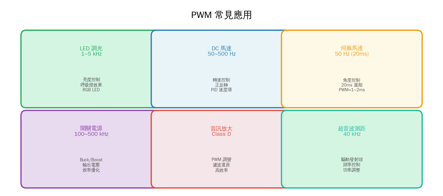
圖 4:PWM 常見應用領域 — LED 調光、DC 馬達、伺服馬達、開關電源、Class D 音訊放大、超音波測距。

文章評論